
With the rapid replacement of mechanical solutions in favor of electronic solutions, many companies are experiencing bottlenecks in new electrical design while at the same time their existing electronics are becoming more complex. These challenges have led to many companies working to maintain old designs rather than implementing new functionality, increasingly so given the component shortages which have been the reality for the past couple of years. How then can this trend be reversed?
One recommendation is modularization, a methodology that has been used in both mechanical and software engineering for decades. This proven solution, when correctly applied, has the possibility to change that trend.
In this article we will briefly explain what an electronics modular system is and discuss some of the benefits.
What is Electronics Modularity?
When discussing the modularity of electronics and PCBs (Printed Circuit Boards), there are two primary levels of modularity.
The first level is the system’s architectural layout, which describes how the electronics are either centralized in one location or distributed throughout the product. A typical example would be where the drive electronics for a motor are positioned within the motor housing. Still, from an architectural standpoint, it may be possible to have the motor drive centralized instead and only feed power to the motor. These types of decisions can significantly impact on the cost and flexibility of the system.
The second level of modularity for electronics is the PCB level which describes how the electronics into one physical location can be divided in multiple PCBs or integrated into one PCB. When integrated into one, there may be the possibility to reuse logical parts of the design even though the physical realization of the PCB will vary with configuration. This is the level of modularity that we will discuss further here.
Based on this criterion, an modular electronics system describes how electronics are divided into modules and how these modules are interface with each other. Additionally, each module has corresponding rules for qualifying variants and how these are configured to create a solution that fulfills the required function.
Typical Electronics Pain Points
Bottlenecks in electronics design resources often result in companies falling short of meeting their product portfolio goals for updates and releasing additional functionality. Some typical causes for this situation can include:
- Engineers maintain old designs with quality problems, replacing last-time-buy components, adding alternative parts, or making minor improvements to existing designs.
- System/product verification consumes critical resources and often results in a re-design before release, which in turn may require rework in the industrialization and production setup.
- Increased component shortages due to disrupted supply chains. Managing the shortages by outsourcing components to various suppliers generates additional work in effort to avoid production stops.
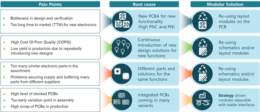
Figure 1: Typical PCB Electronics pain points in design and production
A Better Way with Modularity
A modular design with a high degree of reuse of proven design blocks (Modules) and a reduced number of unique parts in the product design can improve this situation. A modular electronics design will also significantly improve the ability to quickly introduce the latest design throughout the product portfolio with reduced effort and time-to-market (TTM). By having a high reuse of the proven modules, quality problems will be reduced, and electronics engineering resources spent on product maintenance can instead shift to developing new designs.

Physical and Logical PCB Modules
One key decision when discussing PCB modularity is if the components should be laid out on multiple boards or if they should be integrated into a singular board. A split in multiple boards will make the solution more configurable, whereas a shared main board is combined with one or more daughter boards. However, there may be significant penalties for this in component cost, robustness, and geometrical size.

Figure 2: By splitting into multiple boards can vastly reduce the number of items to source and keep in stock. In this example, eight items can be configured to 36 different solutions.
Another solution is to identify logical modules to be placed on a single PCBA. This configuration will not have the same supply chain advantages, but it can still have considerable benefits in engineering and testing for both hardware and software.

Figure 3: PCBA Configuration from Schematic/Layout Modules
Physical Modules – Big Effects on Component Complexity in the Supply Chain
Physical PCB modules will have both geometrical interfaces (spatial constraints, mechanical attachments) as well as electrical interfaces to transfer signals and/or power. Physically the boards can be connected by cables or by board-to-board connections.
The cabling harness can be seen as a module of its own with module variants or as a part of a Module if the cable variants are not significantly generating additional module variants. The focus on reducing cable variants depends on the effort needed to manage variants. If the cable harness is manufactured close to the final assembly, the effort is limited, but if the manufacturing is outsourced to a distant factory with long lead times, a reduction in the variance is of importance.
Logical Modules – High Design Reuse
If it is not feasible to create physical modules where the same part is reused in different configurations, there may still be possibilities to benefit from modularity and the reuse of design. Reuse can be facilitated on the logical level instead if components, schematics, and layouts can be reused across multiple PCBAs. In this case, the supply chain will still have to source or manufacture many different PCBAs, but there are other remedies for that as well with automated production and assembly. All processes can benefit from harmonized layouts.
Four Types of PCB Modules
The first step of PCB modularity is to harmonize the components used. If we, for example, can manage all products with the same processor, there are large benefits for the software development and sourcing function.
The second step of PCB modularity is to design schematics that include multiple components which describe a functional unit in the solution. This type of schematic is typically isolated to a specific function, e.g., RF communication, and there may be alternative variants of it for different purposes, such as BTLE, Zigbee, or Wi-Fi.
The third step of PCB modularity is the layout module, which can be seen as a part of a larger PCBA. This part reserves space on the real PCB and specifies the positions and types of interfaces.
The fourth step is to split the module into a separate PCB – a Physical Module above.
Lower-volume product Modules could benefit from the full-scale advantages by creating pre-built physical variants. While at the same time benefitting from prepared layout modules or schematics that can be used in high-volume products where further optimization can be afforded. This way, TTM benefits from the design and testing of all cases, and lower-volume products can benefit from scale advantages by volume consolidation.
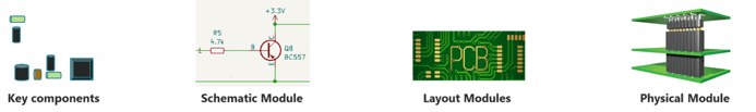
Figure 4: The advantages of PCB Module types increase as we move towards physical modules.
Electronics Interfaces
A foundational activity to fully unlock the benefits of electronics modularity is to define stable interfaces. The interfaces are what allow for reuse and module development over time.
An electronics system often has several system interfaces, e.g., system voltage, I2C bus, SPI, and cooling. Because many modules use these system interfaces, they are critical to define and govern. A small change to these will cause substantial consequences in the system design. Interfaces used for sub-system verification have a characteristic specification for verification testing. Also, interfaces for production test and/or software loading are essential to define and keep as stable in placement as possible between designs to enable the reuse of production equipment for programming and testing.
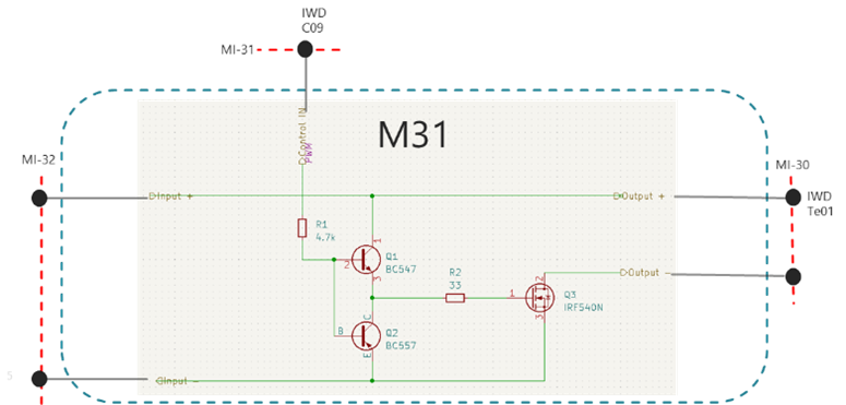
Figure 5: Example of Electronics Schematic Module Interface
Electronics Modularization is a Cross-Functional Effort
Since modularization can have benefits across the value chain, not only isolated to R&D, it is vital to see it as a cross-functional effort. All key stakeholders need to be involved, e.g., product management, sourcing, production, after-market, and sales. This cross-functional involvement ensures that all relevant viewpoints and needs are captured. A tool for doing this and highlighting the intention of each Module is Modular Function Deployment (MFD) which is just as applicable to electronics as it is to mechanics and software.
.png?width=603&height=324&name=Module%20Strategy%20according%20to%20Modular%20Function%20Deployment%20(MFD).png)
Figure 6: Module Strategy according to Modular Function Deployment (MFD)
Benefits of Electronics Modularization
With a Modular System for electronics, design resources stuck in the maintenance of the existing portfolio can be freed and instead develop new functionality for winning products. The Modular System will also enable the launching of new functionality faster across the portfolio.
But the benefits of modularization spread outside the walls of R&D. In production, the introduction rate of new designs will slow down, limiting the investments in tools and test equipment, and the yield problems usually associated with the introduction of a new product will be reduced.
While the purchasing power resulting from fewer parts in higher volume per part is a benefit sourcing will receive that will result in lower cost, supply security, and resilience.
Additionally, the aftermarket business will benefit from the reduction of unique parts. With more common spare parts between products, the service level to customers will increase at the same time as the warehouse and tied-up capital of spare parts goes down.
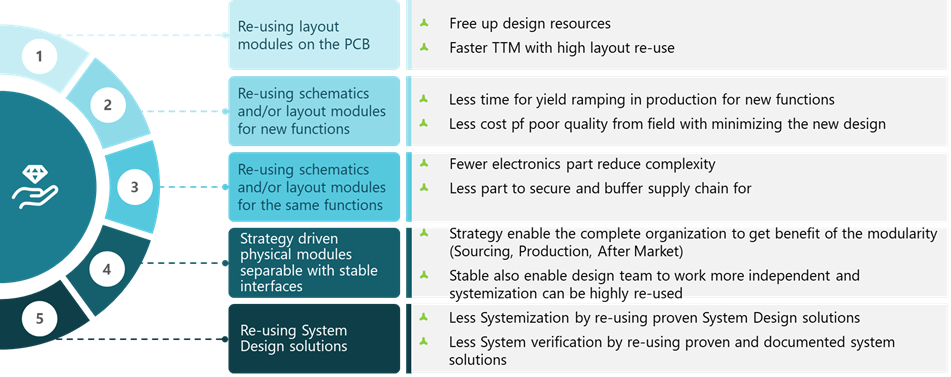
Figure 7: Modularity Benefits
Summary
As we have explained in this post, electronic modularity can reduce complexity and help you focus on innovation rather than maintenance. Even companies that can’t define physical electronics modules see significant benefits from reusing components, schematics, or layouts. Further in-depth articles within the area of modular electronics will follow. Stay tuned!
We are always interested to hear your story and discuss how you can improve from where you are, let us be your sounding board. Contact me directly via email if you'd like to discuss the topic covered or have general questions about modularity. Additionally, feel free to contact us with the use of our contact form.
 AUTHOR
Björn Rosenquist
Senior Manager
+46 70 931 4392
bjorn.rosenquist@modularmanagement.com