
According to Wikipedia, a design is a plan or specification for the construction of an object or system or for the implementation of an activity or process, or the result of that plan or specification in the form of a prototype, product, or process. The verb to design expresses the process of developing a design. Wikipedia further defines configuration design as a kind of design where a fixed set of pre-defined components that can be interfaced (connected) in pre-defined ways. is given, and an assembly (i.e., designed artifact) of components selected from this fixed set is sought that satisfies a set of requirements and obeys a set of constraints.
A successful modular system has three characteristics: Flexibility, Agility, and Efficiency. When creating the modular system, the modules and interfaces should be carefully selected to ensure that the three characteristics are exploited to enable company strategy. However, while modules and interfaces may be abstract and fussy, the design of the modular system must take this abstract and strategic level to a very detailed and exact design, and while doing so, ensuring that the original intention of flexibility, agility, and efficiency is kept. Simply put, we want to design for configuration, design for reuse, and design for future development.
The design of a modular system should ensure:
- Reuse modules and module variants to reduce the cost of complexity, and that economy of scale effects can be reached.
- Interface control to ensure that the modular system remains efficient over time.
- Possibilities to configure products based on modules, to reduce order-related design work, especially for customized products
Many modern CAD solutions can be utilized for the configuration design of a modular system. But understanding the ambition and targets of the modular system is key to use the tools the right way. We want to use the CAD tools to ensure high quality and high efficiency in the design work. Using the wrong tools or functions compared to what we need, we may spend a lot of work on architecture design without significant benefits. On the other hand, if we are not documenting enough, we risk deteriorating the value of the modular system.
In this blog post, I explain some key concepts for designing for reuse and configurability and touch upon what you need to consider to be successful.
Top-down Design of the Modular System
The traditional way of handling design work, with a product or project-specific solution and structure, is not the answer. Surely, there could be design for reuse, but the process of designing and managing products should be aligned with a modular system. With Top-down design, the development work focuses on the complete modular system development, encompassing the entire product range, to prevent falling back into single product development.
Ideally (?), the module variants of a particular module share many requirements, as exemplified in the image below, depicting two pulleys. These makeup variants of a common pulley module in a modular system. Note that the bolt connection design is shared between the module variants. This is the interface that must be standardized and govern to enable reuse and configurability over time.
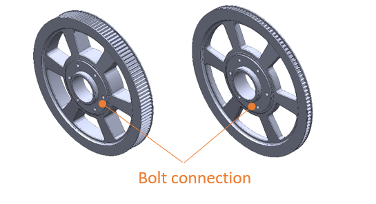
Identifying these commonalities across variants gives an opportunity from a design perspective to collect these common requirements at an early stage and drive respective module variant design with the use of them.
Designing Modules to Ensure that the Requirements of the Modular System are Fulfilled
A module should be designed with a top-down approach to the requirements of the modular system. By using a skeleton model for each module in which envelope and interface objects are included, module variants can be designed based on this skeleton model. This way of designing the modular system ensures that the module requirements are fulfilled by each module variant.
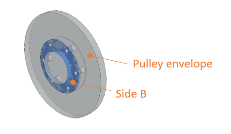
The image below shows an example of how the architectural model of the pulley module could look. The model contains the bolt connection and boundaries for the pulley diameter.
Designing Module Interfaces
Keeping a pre-defined library of interfaces and module envelopes enables improved control over the architecture from a technical product and design management perspective. During complex development projects, the risk of miscommunication between designers is ever-present, resulting in incompatible components needing expensive and time-consuming corrections. Further, there is always a risk of product information being lost when people move around in the organization and so, maintaining interfaces is difficult if it is solely up to the manual transferring of information from one designer to another.
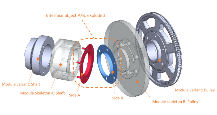
To make sure that the outcome (in terms of designed module variants) uses the defined standardized interface, this interface object should be created once and then reused. An interface always has two sides, for example, a bolted flange (Side A) and its corresponding hole pattern flange (Side B). The two-sided interface object is created once and each module and module variant created inherits the geometry from the corresponding side of the interface object, as shown in the image below, illustrating the interface between a belt pulley and a machine shaft.
The module interfaces are by many seen as the most important asset of a modular system. They are both what enables flexibility, but they are also what we need to design in a robust way to ensure agility. Why? – If we need to change an interface, it will have a ripple effect on both sides of the interface. Worst case, it may even have ripple effects on other interfaces as well. In a strict sense, changing interfaces means changing architecture.
This importance highlights the topic of modular system and interface governance. If the interfaces are to be kept intact over a long time, we must have ways of identifying when change is needed, we must have ways of deciding if the change request is accepted or not, and we must also have ways to validate that new designs fulfill the rules of the applicable interfaces.
To build a design support that fulfills the complicated variance in a modular system for a complex product, a toolset to handle the effect of varying size of module variants, product assemblies, and differences in interfaces that will occur in the product, is needed.
Module Variant Design in Practice
Managing the common requirements for module variants by using skeleton models on the module level not only makes the reviewing and validation of these objects easier but also improves the design process of the module variants. Common requirements for a module and geometry for an interface are clearly presented as input to the designer that will create the parts for a certain module variant.
By documenting the module requirements in a geometrical model, it is also possible to share the work among a group of designers to increase speed. It also supports handing-over of design work between resources if the designers change over time. Remember that the most successful modular systems live for a long time. This makes it even more important to ensure that person dependency on specific experts is avoided.
When the design work of a module variant is started, the designer starts by importing a module skeleton into their 3D environment. This skeleton comes with pre-defined interfaces mounted on a module envelope. Complete liberty is given to the design if the boundary conditions given by the skeleton are met. In other words, it is not possible to create a module variant that exceeds the envelope for a module, is not equipped with the correct interfaces, or in any other way is incompatible with the modular system.
Not only is this aiding the design work by saving time and effort for the designer. Changes done to the product architecture, such as a design change in an interface, will automatically update the design across the modular system, of all module variants affected by that interface, as exemplified in the figure below, where one side of an interface object drives the design of all variants of a module.
Enabling Configuration Design with Smart Modular Design
A key benefit of a modular system is that it aids the designers in their everyday work. In a top-down design system, each modular design element – interfaces, envelopes, etc. are part of a modular framework. The module skeletons, envelopes, and interfaces used by the design department are controlled by parameters set in the modular architecture. Changes to these properties can even carry over to the design elements without the need for manual updating.
When building a modular system for a complex product, a significant part of the configuration rules are typically set by practical limitations from the design. For instance: an architecture for a passenger car program might include several sizes of chassis and engine performance steps. It might seem logical from a modularization perspective to allow full liberty in pairing chassis and engine. However, it might be so that the smaller chassis is not fit for the largest engines and vice versa. For a product with high combinatorial level, handling the variance in a more traditional way, such as a 150% BoM or a super-BoM, will become very impractical since it relies on manual input of all possible combinations of parts. A modular BoM combined with a configurable modular design is updated with significantly less work.
Configuration design in combination with a modular BoM also limits the amount of geometrical testing needed when new module variants are introduced. Modular skeletons ensure that all variants fit the requirements on the module and the configuration rules ensure that only viable combinations of modules and module variants are tested - geometrical testing is limited to where it is needed.
Three Points for Succeeding with a Flexible, Efficient, and Agile Modular System Design
What is the purpose of the transformation to configuration design? The implementation of a new methodology should always be based on a clear understanding of the purpose. To implement a modular system design that serves the cross-functional purpose t is of vital importance that the team gathers the expectations from all parts of the organization that are affected by the change and understands how these expectations affect each other.
Point 1: Set the ambition level – for the transformation into a top-down configuration design to be successful, it is important to ensure that the ambition level matches the expectations from the organization. What is the intention of the transformation? What level of integration should the design work have in the modular architecture management system? Setting the ambition level is also important in the details – which level of detail required for skeleton and interface models is a tradeoff between resources needed to create and maintain these objects and the level of aid they give to the designer. Be pragmatic.
Point 2: Base the skeleton and interface models on the demands set by the modular system – a common practice when designing for the manufacturing industry is to base the design of new components based on old, similar parts. When we create the models for the interfaces, skeleton models, and envelopes it is important that they reflect requirements from the current architecture and not old design decisions that might be related to a specific manufacturing method, an old manufacturer, or other design requirements that are no longer applicable.
Point 3: Choose tools and methods that match the purpose – it is of key importance that the tools for product management and design work are chosen and integrated to a level that matches the purpose of the design workflow and method.
Summary: Configuration Design for flexibility, agility, and efficiency
A modular system increases the flexibility, agility, and efficiency of a company by ensuring that modules and interfaces are created in a way that exploits these characteristics and aligns them with company strategy. Combining the modular system with smart, top-down modular design enables the gains made by the architecture to be carried over into the product design. In this article, I explained some key concepts of design for configuration, reuse, and future development and how to boost the benefits of modularization with configuration design.
Traditional single-product development, with a structure based on products or projects, disengages the design work from the modular system. With Top-down configuration design, the focus is on the complete product architecture development, encompassing the full product range.
Typically, variants of a module share a lot of commonalities: interfaces are standardized and the physical envelop of the module is typically also governed by requirements on the module level. By collecting these requirements in module skeletons that the designers use as a base in the design work, we can drive the module variant design with help from the requirements set by the modular architecture.
When the design work of a module variant is started, the designer starts by importing a module skeleton into their 3D environment. Complete liberty is given to the design if the boundary conditions given by the skeleton are met. In other words, it is not possible to create a module variant that is incompatible with the modular system. Further, changes made by the product management that affects interfaces or other requirements can be carried down to module variant level without the need for manual transfer of information.
Modular design in combination with a modular BOM also limits the amount of geometrical testing needed when new module variants are introduced. Modular skeletons ensure that all variants fit the requirements on the module and the configuration rules ensure that only viable combinations of modules and module variants are tested - geometrical testing is limited to where it is needed.
We have listed 9 popular CAD solutions that all support configuration design. Download the list below.


AUTHOR
Oscar Strömberg
Consultant
T: +46 8 456 35 00
E: oscar.stromberg@modularmanagement.com